Software Architecture
- what is software architecture -
- high level design - hide implementations and express in terms of abstractions
- of the different components
- and how they interact with each other
- to fulfil requirements (what it should do) and constraints (what it should not do)
- “software development lifecycle”
- requirements
- design
- implementation
- testing
- deployment
- maintenance
- difference between “waterfall” and “agile” - in agile, we keep iterating over and over on the above steps, and the method is incremental, unlike in waterfall, where we assume that for e.g. the requirements are final
- software architecture is the output of the first step / input to the second step
- decisions at the bigger level cannot be changed easily, cost a lot of wasted effort, etc so we need to think first
System Requirements
- the scope of the problem / the number of ways to solve a problem increases as the abstraction increases from designing a method -> class -> module -> application
- the ambiguous problem needs to be converted to a technical problem
- we might need to ask clarifying questions to the client
- different types of requirements -
- features of the system
- quality attributes
- system constraints
Features of the System
- express the actual “functional requirements” of the system
- e.g. hitchhiking service - allow users to share rides
- identify all the “actors” and “use cases”
- expand each “use case” through a “flow of events” - we can use a sequence diagram for this

Quality Attributes
- to address the “non functional requirements” of the system
- how well a system should perform in a particular dimension
- important quality attributes include performance, scalability, availability, fault tolerance, etc
- have a direct impact on the technical decisions of the system unlike features of the system
- e.g. show products when searched for under 100ms, system should be available 99.9% of the time, etc
- they have to “measurable” and “testable”
- need to make “tradeoffs” - there is no one architecture that can address all problems
- sometimes, clients might make “infeasible” requirements - 100% availability, unlimited storage, etc. we should call them out
System Constraints
- limitations and boundaries of a system
- three types of constraints - technical, business and regulatory
- “technical constraints” - e.g. lockin to a particular database, cloud vendor, software license, etc
- “business constraints” - time and budget limitations
- “regulatory constraints” - e.g. location specific
- we should avoid tight coupling, else we would have constraints specific to hardware etc
Important Quality Attributes
Performance
- “response time” - time between client sending a request and receiving a response
- response time = “processing time” + “waiting time”
- processing time - time spent in performing the actual business logic
- waiting time - time spent in transit, waiting queues, etc
- waiting time is also called “latency”, while response time is also called “end to end latency”
- response time is critical when a request is in the path of a user interaction - users do not like to wait
- “throughput” - can be
- either “number of tasks performed per unit of time”
- or “amount of data processed per unit time” i.e. bits per second etc
- throughput can be useful when for e.g. analyzing a constant stream of logs from several sources
- consideration 1 (response time) - e.g. we as developers think our processing time is 10 ms so response time is 10ms, but assume our server can only process one request at a time
- if we get two concurrent requests, the waiting time for the second request will be 10ms, thus increasing its response time to 20ms
- so, response time is affected by waiting time as well
- consideration 2 (response time) - response times for some requests in our system will be very bad, while all others would be relatively better
- these relatively slow response times are called “tail latency”
- so, instead of metrics like median or average, the most effective way to measure response times is a “percentile distribution chart”, instead of just using median or average
- in this chart, the “xth percentile” is the value below which x% of the values can be found
- refer the part around 100th percentile in the percentile distribution graph below for tail latency
- so, we would set slo like so - 95th percentile of requests should have 30ms response times

- consideration 3 (both response time and throughput) - effect of load - the point where the response time starts increasing / throughput starts decreasing due to increase in load is called the “degradation point”

Scalability
- the load on our system never stays the same - seasonal traffic e.g. during holidays
- “scalability” - systems capability to handle growing amount of load
- scalability are of three types
- “vertical scalability” - adding more resources / upgrading existing resources on a single machine
- advantage - no code changes are needed, migration is straightforward
- disadvantage -
- there is a limit to which we can scale vertically
- does not provide high availability or fault tolerance
- “horizontal scalability” - adding more instances on different machines
- advantage -
- no limit to scalability
- more importantly - provides high availability or fault tolerance
- disadvantage -
- code changes might be required
- overhead around coordination is introduced
- “team / organization scalability” - as we add more engineers, productivity decreases after a certain point
- we can split codebase into separate modules or better, architecture into separate services to decrease conflicts
Availability and Reliability
- availability = uptime / (uptime + downtime)
- 99.9% means ~9h of downtime in a year
- mtbf - “mean time between failures”. it is the average time the system is operational
- mttr - “mean time to recovery”. it is the average time the system is non operational i.e. time taken to detect, diagnose, repair and test
- so, reliability = mtbf / (mtbf + mttr)
- so, one way to ensure high availability is to reduce mttr i.e. detect and resolve issues in near 0 time
- note - availability != reliability
- “availability” - how often the system is accessible when needed
- “reliability” - how consistently a system performs without failure
- “maintainability” - means mttr
Fault Tolerance
- there can be “human errors” (e.g. faulty config), “software errors” (out of memory exceptions), “hardware failures” (infrastructure issues / outage), “network failures” (e.g. router / cable failures)
- failures are inevitable
- “fault tolerance” - helps keep system operational (i.e. available) despite failure of multiple components
- fault tolerance tactics - prevention, detection / isolation and recovery
- “failure prevention” - eliminate single points of failures. use “replication” and “redundancy” for this. two strategies -
- “active active architecture” - requests can go to any replica. so, all of them have to be kept in sync. so, if one of them goes down, the remaining one will still continue to operate. advantage - helps balance load, since it is like horizontal scalability. disadvantage - keeping all replicas in sync is non trivial
- “active passive architecture” - one primary replica takes all the requests, while the passive replicas take periodic snapshots of the active replica. disadvantage - we cannot scale our system horizontally, since we are still restricted to the one active replica. advantage - this leader follower pattern is much easier to implement
- other terms to describe these - “redundancy”, “failover”, “replication”
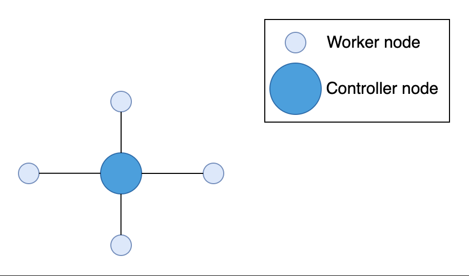
- “clustering” - grouping similar, multiple servers together. even if one machine / server in the cluster fails, others in the cluster continue to function, thus providing fault tolerance
- “check pointing” - all individual processes in the distributed system save their own checkpoints. this helps them come back up in case of a failure. in case of failures, we restore to the checkpoint, and any in-process operations are rolled back as if they never happened
- “failure detection / isolation” - if we have a faulty replica, our system should be able to detect it and isolate it
- this is done by a monitoring service using -
- health checks - monitor service polling the servers periodically
- heartbeats - the servers sending heartbeats to the monitoring service periodically
- monitoring service can be more complex - declare a host to be failed based on its error rate, if its response time has suddenly increased, etc
- “failure recovery” - some strategies -
- stop sending traffic to the faulty instance
- attempt to restart the host
- “rollback” -
- rollback service to a stable version
- rollback databases when it reaches an inconsistent state to a previous consistent state
SLA, SLO and SLI
- sla - “service level agreement” - agreement between the service provider and client
- if we fail to deliver these sla, we have to provide refunds, license extensions, etc to clients
- slo - “service level objective” - goals we set for our systems
- each slo can represent one of the quality attributes
- an sla is basically a collection of slo
- even if we do not have an sla, we should have slo so that our users know what they can expect from us
- sli - “service level indicator” - quantitative measure of the different quality attributes
- achieved using monitoring services
- we can compare what we see in sli to what we define in slo
- this is why we said quality attributes should be measurable and testable - otherwise, we would not have been able to measure our slo using sli
- general guide - based on what clients ask, we should define slo and then find out matching sli
- another technique - define loser external slo but stricter internal slo
Centralized Architecture
- note to self - use same points when asked about client server architecture
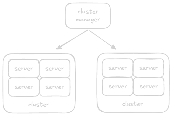
- “centralized architecture” - we have a single “server / controller node”, and several “client / worker nodes”
- server node distribute the tasks, while the client nodes perform the actual task
- “global clock” - all client nodes sync their clocks with the server’s clock
- advantage - easier to implement, monitor and manage
- disadvantage - single point of failure
- e.g. - monolith, layer architecture, etc
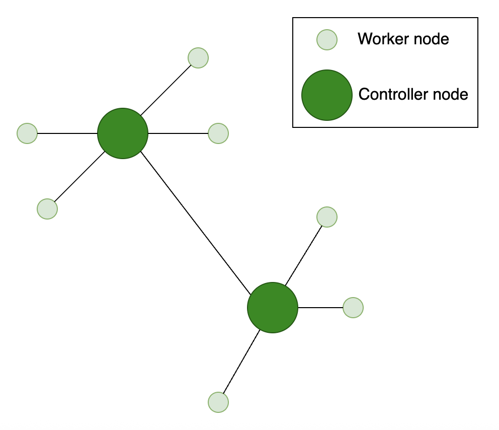
Decentralized Architecture
- note to self - use same points when asked about peer to peer architecture
- “decentralized architecture” - the system’s behavior is not controlled by a single server node, but the decisions made by each node’s individual decisions
- each server node has its own set of client nodes
- “node failure checks” - we divide the task into two identical parts and execute them in parallel. if the output from both subtasks is same, we can be sure that our system is working. else, there is a potential issue with our node. this allows us to respond to failures automatically
- there are several architectures - “pure” (all nodes are equal and there is no central server), “hybrid” (some nodes might have special responsibilities, e.g. indexing), “structured” (nodes are organized into a specific structure), etc
- disadvantage - increased overhead for implementation, monitoring and management
- advantage - more scalable
- e.g. - cryptocurrency, blockchain, p2p (peer to peer), publish subscribe
API Design
- api - “application programming interface”
- the interface is a “contract” between our systems and the client
- our system becomes a “black box” - the client need not know the internal implementation of this api, they just have to interact with this api
- once we define the apis, our clients can start integrating with it without us actually having built its implementation entirely
- it is called remotely over the network
- apis can be public, private / internal and partner
- “public api” - exposed to general public and any developer can call them. might require registration from users first
- “private api” - used by other systems inside the organization, but not exposed outside the organization
- “partner api” - to organizations having a business relationship with us
- two types of apis we discuss - rpc and rest api
Good Practices for API Design
- “encapsulation” - clients should not have to care about implementation
- we can change the implementation without the client changing anything on its end
- “ease of use” - descriptive actions and resources, keeping it consistent
- “idempotent operations” - no effect if the operation is performed > once. updating the address is idempotent, increasing balance by 100 is not
- assume there is an error due to some reason - the request is lost / response to the message is lost (but the request was processed)
- now, the client does not know which one happened
- so, even if it retries the operation, it should not have any consequences
- “pagination” for large responses - the client can provide the offset and the number of items to retrieve
- “asynchronous operations” - some operations are very big, and we cannot provide any reasonable response immediately
- instead of the client having to wait for something like this, we can use asynchronous operations
- the immediate response includes an identifier which the client can use to track the progress of the operation
- “versioning” - allows us to make non backward compatible changes to the api
RPC
- rpc - “remote procedure calls”
- ability of a client to execute a subroutine on a remote server
- “location transparency” - calling an rpc looks like calling a local method
- applications written in different programming languages can also talk using rpc
- idl - “interface description language” - we define the api and data types in this language
- then, the rpc framework we use generates 2 separate implementations - “server stub” and “client stub”
- they include the corresponding classes for the api and data types we define in the interface description language
- so, the idea is our programs just interact with these server / client stubs, and they take care of everything else
- rpc will take care of marshalling / unmarshalling the request / response for us automatically
- it might include propagation of exception etc as well
- rpc helps the clients focus on performing an action on the server systems, and not worry about the network communication
- drawbacks -
- remote methods are a lot slower and unreliable. the client execution will thus be blocked. so, we should try writing asynchronous versions for the remote methods
- it is also not useful when we want the features like cookies, headers etc
- popular frameworks -
- grpc by google - high performance rpc. uses “http/2” for transport and “protocol buffers” as the interface description language
- apache thrift - by facebook. also allows interoperability, e.g. python calling a c++ server
- java rmi (remote method invocation) - unlike above two, specific to java - helps one jvm invoke a method on another jvm
Rest API
- rest - “representational state transfer”
- it is not a standard or protocol, but an architectural style
- advantage - helps maintain quality attributes like performance, availability, scalability and fault tolerance
- an api that obeys the rest architectural style is called a “restful api”
- the only actions a client can take in an rpc api is defined inside the interface definition language - so, it is somewhat static
- in rest, we can use hateoas - “hypermedia as the engine of application state” - the response contains “hypermedia links” around the operations that the client can perform
- rest should be “stateless” - no session information should be maintained by the server
- this way, each request is served in isolation
- advantage of statelessness - multiple requests by a single client can be processed by different horizontally scaled instances
- “cacheable” - the server can declare a response to be as cacheable or non cacheable. if a response is cacheable, the extra round trip to the server is avoided - the response is returned from the cache directly and our server is never even called
- this reduces response time and the load on server is reduced
- “resources” - resources are organized in a hierarchy in using the uri “uniform resource locator”
- a resource can be a “simple resource” or a “collection resource”
- resources can also have “sub resources”
- use nouns only for resources
- “resource identifiers” - should be unique
- for modelling actions, we use the http verbs
- so, unlike rpc, the only actions supported are crud - creating (POST), reading (GET), updating (PUT) and deleting (DELETE) a resource
- GET method is considered “safe” - does not change the state of the system
- GET, PUT and DELETE methods are considered “idempotent” - applying them multiple times will result in the same state change as applying them once
- GET requests are also considered cacheable by default
- the client can send the additional data using json (or xml)
- creating a rest api for a movie streaming service
- identify the resources - movies, users, reviews, actors
- map to uris -
- /users, /users/{user_id}
- /movies, /movies/{movie_id}
- /actors, /actors/{actor_id}
- /movies/{movie_id}/reviews, /movies/{movie_id}/reviews/{review_id}
SOAP
- “simple object access protocol”
- a messaging protocol for exchanging structured data between applications typically over http
- a soap message is an xml document. it has the following -
- “envelope” - the root element specifying the start and end of the message
- “body” - actual payload, can be request or response
- optional “header” and “footer”
- unlike rest, soap has a single endpoint for all requests
- it is known to be more resource intensive due to its use of xml
- its features like caching and security (ssl, oauth, etc) may not be as evolved as rest
Web Sockets
- used for realtime, bidirectional communication between client and server
- it uses a single, long lived connection between the client and server
- use cases - online gaming, chat applications, etc
- first, the connection is established between the client and server i.e. the “websocket handshake” completes
- then, the client and server can begin interacting without the need for a new request response cycle
- uses a “publish subscribe pattern”, where the client subscribes to a specific channel, and the publisher pushes to it. this allows for efficient communication as this way, the client only subscribes to / receives messages relevant to them
- http is half duplex, but websockets are full duplex
- websockets mean more overhead for the server because it maintains a persistent connection for each client
- there is another concept called “push” - the usual method is “pull”, where the client explicitly requests for the data it wants and the server responds with it. disadvantage - overhead due to frequent connections in case of multiple pulls, so not suited for realtime applications. the push method allows the server to push updates to the client
Alternatives to Websockets
- these 3 are alternatives to websockets
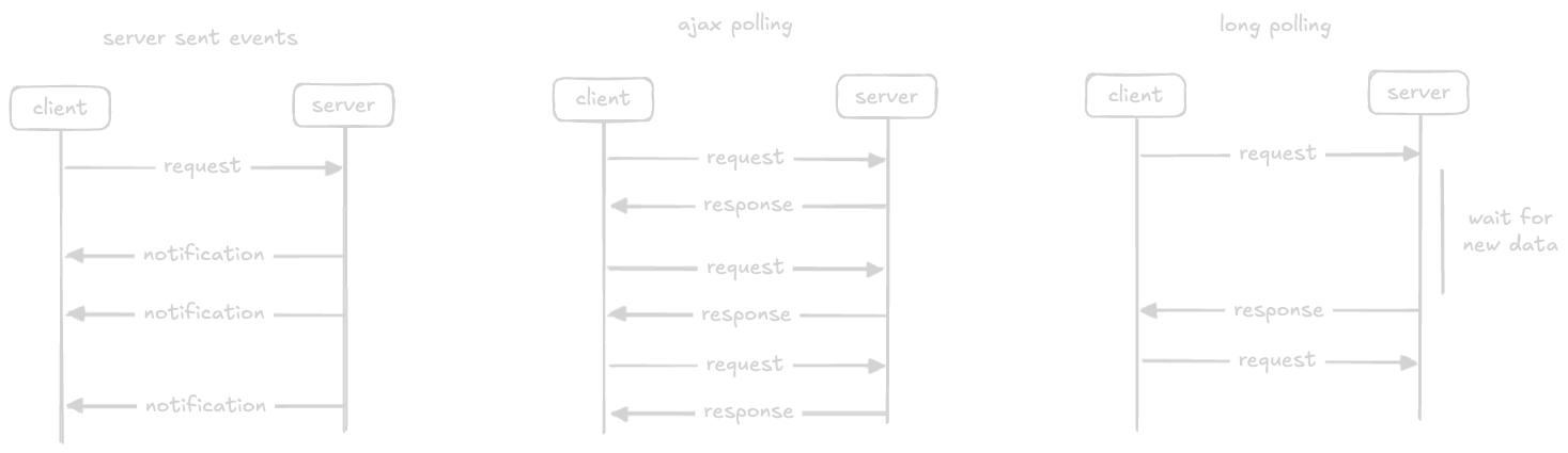
- “sse (server sent events)” - the client establishes a long term connection like in websockets
- however, only the server can send data to the client
- if the client wants to send data to the server, some other technology is required
- “ajax polling” - the client repeatedly makes requests to the server for data
- if there is no data, the server returns an empty response
- “http long polling” - also called “hanging get”
- client requests server, but server does not respond immediately
- it instead holds the request open until there is new data available, instead of sending an empty response
- once the data is available, it sends the response
- immediately after this, the client requests for fresh data again
Ajax
- “ajax” - “asynchronous javascript and xml”
- small parts of the webpage is exchanged without reloading the entire page
- this makes the web application interactive and dynamic
- “ajax request” - the request made to servers to update the web page
- “jquery” - simplifies ajax and other javascript techniques
Large Scale Systems Building Blocks
Load Balancers
- if we run our application on multiple instances due to horizontal scaling, the client applications will have to know the ip addresses of all these instances in advance
- this results in tight coupling of clients to our systems, and makes it hard for us to make any changes
- advantages of load balancers -
- acts as a layer of abstraction between clients and our instances, so it looks like one server to the client
- distributes the load from clients among our horizontally scaled instances equally
- “autoscaling policies” - easily add / remove instances to the fleet based on requests per second, network bandwidth, etc, and all of this is hidden behind a single load balancer
- “fault tolerance” - load balancers can be configured with “health checks” to avoid sending traffic to unhealthy instances
- rolling release - we can perform maintenance tasks easily by pulling down hosts one by one, and the load balancer would not direct traffic to these hosts
- can provide “tls termination”, thus reducing overhead on end servers
- “connection draining / graceful shutdown” - during for e.g. scaling down, stop sending new requests but let the inflight connections finish
- types of load balancers - dns, hardware, software and global server
- “dns load balancer” - dns maps human friendly urls to ip addresses
- “dns record” is the response by “dns servers” when asked for ip addresses for a url
- can return multiple ip addresses in this record, ordered differently every time using round robin
- the clients typically pick the first address from this list, and we achieve load balancing this way
- disadvantages -
- dns servers do not perform health checks, so can return ips of faulty servers
- the dns record can be cached at client, which means they can call the faulty instance till the ttl - “time to live” expires
- exposes the ip addresses of our instances directly, thus exposing implementation details
- not efficient enough to route to the closer data center
- dns packets are small (for efficiency). so, they cannot include all the ip addresses
- “hardware load balancers” and “software load balancers” address all these issues
- hardware load balancers run on hardware optimized for load balancers
- software load balancers can run on any general purpose machine
- all the communication is done through the load balancer, thus making our systems much more secure - in dns load balancing, it was happening directly once the client got the ip addresses
- they can monitor the health of our instances and only route traffic to the healthy instances
- they also allow for more advanced setup like take the instance type into account - some instances in our fleet might be more powerful than others, use more powerful techniques like current requests per second when load balancing the traffic, etc
- nowadays, we have also have the concept of “cloud load balancers”
- disadvantages -
- typically, hardware and software load balancers are located close to the instances. so, if we run our load on multiple geographical locations called data centers, one group of the instances will have the load balancer located far away
- also, load balancers do not solve the “dns resolution” problem on their own - load balancers are again just an ip address, and we need to map it to a more human friendly url
- the load balancer is behaving like a “reverse proxy” in this case
- “vip” or “virtual ip” - basically, the outside world only sees one ip address. however, behind the scenes, it automatically load balances between multiple servers, handles failover, etc

- “global server load balancer” - more intelligent than the typical dns load balancer
- it can redirect clients to the data center geographically closer to them, the location that will send a faster response time (this can be different from just using the geographical location due to number of hops), etc
- there is a load balancer deployed at each of the data center
- also, gslb can handle outages in one data center by not routing traffic to this faulty data center

- open source software load balancers - haproxy, nginx
- cloud load balancers - aws elb, which has various types as well
- global server load balancer - route53
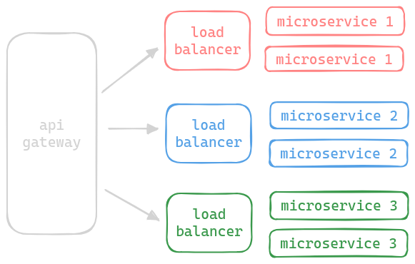
- load balancers are also called “dispatchers”
- if using microservices, we can have a dispatcher for each micro service, and each microservice can be individually scaled
- below, we use load balancers both for communication from outside and internal clients

Miscellaneous
- there can be different tls strategies -
- tls termination - decrypt at lb
- tls passthrough - lb forwards as is. required for mtls like strategies
- reencrypt - decrypt for l7 routing, and then reencrypt back again
- backend sees lb ip, not clients
- layer 7 load balancers add headers like
x-forwarded-for,x-real-ip,x-forwarded-proto - layer 4 load balancers - they do not know about the actual protocol. it could be postgres, redis, http, anything. they just deal in tcp. so, they instead prepend some text about the ip address. this way, the backend reads the first line and understands the actual client ip
- layer 7 load balancers add headers like
Message Brokers
- also called mom - “message oriented middleware”
- “synchronous communication” - both sides - client and server need to be healthy and maintain an active connection either with each other or via the load balancer - this is good when the server takes a short time to process and respond
- “message broker” - a queue data structure to store messages between senders and receivers
- message brokers helps with “asynchronous architecture”
- it entirely decouples senders from receivers - the sender does not wait for a confirmation from the receiver - it just puts the message onto the broker. this adds a lot of fault tolerance - receivers can be down and still receive the events when they come back up. they also prevent messages from being lost. in synchronous systems, it can happen that the request / response is lost, and the client will never know which one it was, and it might retry, which would lead into further issues if the request is not idempotent
- e.g. the users see a success screen immediately after placing an order, while they get an email later if the order is placed successfully. this placing of an order involves a chain of services like order service, payment service, notification service, etc, and the client gets an immediate response with all this being handled behind the scenes
- message brokers are generally not exposed to outside world unlike load balancers
- it acts like a buffer when there is an increase in the load - assume we use synchronous communication - if there is a sudden spike, we will we will receive a lot of requests concurrently, which can result in our system crashing, dropping requests, etc. this is solved using asynchronous communication
- it can help with load balancing - multiple instances can listen for an event and the message broker will send it to one of them
- it can also perform transformations on these messages, thus helping with streaming analytics
- open source message brokers - rabbitmq, kafka
- cloud message brokers - sqs
API Gateway
- we break our services into smaller services due to the organization scalability
- the client will also need to now know about the different services - one service for fetching videos, another for fetching comments and so on
- api gateway helps with “api composition” - we compose all the different apis in all our services into one single api that the clients can interact with
- now, each service will need its own authentication and authorization. api gateway helps eliminate the duplication of auth logic - api gateway supports not only authentication but authorization as well
- we can have different apis for mobile vs desktop applications, and the client would be abstracted away from all this - backends for frontends pattern using user agent header
- api gateways can perform “ssl termination” - the traffic is encrypted between clients and api gateway, but decrypted between api gateway and servers
- api gateway can also implement “rate limiting” to prevent dos “denial of service” attacks
- without an api gateway, the client will make a call to fetch the home page, another call to fetch the video and finally another call for all the comments of this video. using “request routing”, api gateway makes all the calls itself and sends the aggregated response to the client. this helps improve the performance a lot, since we are saved from these multiple requests going over the internet
- “static content and response caching” - caching to reduce response time for client
- it supports monitoring as well to not route traffic to unhealthy instances
- it can perform “protocol translation” - the api gateway exposes a rest api, while the underlying services use soap and xml, grpc + protocol buffers, etc
- considerations - api gateway can become a single point of failure - deploy multiple api gateways sitting behind a global server load balancer
- do not put business logic into api gateways
- open source api gateway - netflix zuul
- cloud api gateway - amazon api gateway
Note - Load Balancers vs API Gateway
- load balancers are only for balancing load among identical “servers”
- api gateway is the “public facing interface” that routes traffic to “services” and not “servers”
- so, a common pattern is that an api gateway routes traffic to load balancers, which can then route traffic to the individual servers
- apart from that - feature sets of both are different -
- load balancer is more around the different routing algorithms, performing health checks, etc
- api gateway is more around api composition, auth, request routing, protocol translation, throttling, caching, ssl termination, etc
- so, a load balancer might be enough for internal, individual services, while we might need an api gateway for public facing services
CDN
Problems
- even with hosting on multiple data centers, there is significant latency between end user and server location
- first, the 3 way handshake happens
- then maybe the html is served
- finally, all static assets like images are served
- this involves multiple network round trips and hops from the client to the server
- users do not wait for long for websites to load - they typically abandon it
- also, different network paths have different kinds of issues - e.g. different “path mtu”, different levels and types of network congestion characteristics, etc
- note - “path mtu” - path message transmission unit i.e. the largest packet that can be transferred without the need for splitting it into smaller parts
- lot of redundancy when duplicate content needs to be served to multiple users
- this usual method of servicing traffic from the datacenter does not scale to millions of users
Solution
- cdn - “content delivery network”
- we can get the static content like htm, css, js, images and videos closer to our end users
- cdn is a “globally distributed network of servers”
- the servers are called “edge servers” because they are placed on the “edge network” i.e the interface between the local network and internet
- these are also called “proxy servers” as they are a proxy between the server and client
- the location the cdn servers are present at are called pop - “points of presence”
- page loads are faster now
- additional advantage 1 - cdn also protects us against ddos attacks - cdn network is much larger and distributed than an attacker is capable of, so it can absorb large amounts of traffic easily
- additional advantage 2 - cdn also uses technologies that are more optimized, like using storage optimized for delivering static content, compressing using algorithms like gzip, minification of files, etc
- additional advantage 3 - tls termination - cdn can handle the overhead of establishing and maintaining secure connections with clients. tls connections are cpu intensive, and involve multiple trips
- there are two strategies we can use - pull and push
- “pull strategy” - we tell cdn which content it should cache, and how often this should be “invalidated”, which is configured by using a “ttl” property
- the first time, the cdn has to make the request to our servers to cache it
- however, subsequent requests are served by the edge servers of the cdn directly
- after the expiry, the cdn will send our servers a new request to check if the asset has changed, and accordingly refresh the cached asset
- disadvantages -
- servers need to be available (first time or when ttl is reached) in order to serve the response
- first request after ttl is reached is slow
- “push strategy” - we publish the content to the cdn directly when the new version of the asset is available
- so, we typically do not set a ttl / set a very long ttl in this
- advantage - using the push strategy, the dependency on our servers to stay available is removed
- disadvantages -
- not suited for long tail content - infrequent content gets pushed, thus consuming bandwidth and resources
- not desirable for frequently changing content, since it would require frequent invalidations and pushes
- best approach - use the push model for “static content” and pull model for “dynamic content”
- examples - cloudflare, amazon cloudfront
Cloud Computing
- cloud is mostly based on iaas - “infrastructure as a service”
- gives us access to virtually infinite compute, storage and networking
- we only pay for what we use / what we reserve, thus saving costs
- we can improve our scalability and reliability by deploying our software to multiple “regions” and “zones”
- disadvantage of cloud computing - we do not have access to the infrastructure
Scalability Patterns
Load Balancing Pattern
- synchronous communication - can be implemented using load balancers
- asynchronous communication - can also be implemented via message brokers
- note - load balancing != load balancer, so do not get confused
- note - message brokers are not exposed outside, so they cannot be used via client directly unlike load balancers
- when using cloud, both load balancers and message brokers are built with redundancy and replication in mind to increase fault tolerance
- there are various “routing algorithms” used for load balancing. we discuss three of them below - round robin, sticky session and least connections
- “round robin”
- the simplest / most common / default algorithm
- routes each request sequentially to the “next” worker instance
- disadvantage - only works when application is stateless - each request by a client can be handled in isolation by any one of the target servers. it will not work when an “active session” is maintained between a client and a server
- a variation can be “weighted round robin”. useful to direct for e.g. more traffic to more powerful servers
- “ip hash” - when the client ip address hash is used to determine the server to direct traffic to
- “sticky session / session affinity” -
- use cases -
- auth information of a client is stored in session, so that it does not have to reauthenticate repeatedly
- a client uploads a very large file in parts. the different parts need to go to the same server for reconciling
- requests from the same client are always sent to the same server
- this can be achieved using a cookie / by inspecting client’s ip address (combine with ip hash algorithm)
- disadvantage - this only works for smaller sessions - otherwise, the same server might end up with too many longstanding connections
- use cases -
- “least connections” -
- route the request to the server with least number of open connections
- so, it solves the problem we saw with sticky sessions
- use case - like sql, ldap, etc
- “least response time” - direct to the server with the smallest response time
- “resource based” - direct to the server with the most available resources like cpu, memory, etc
Pipes and Filters Pattern
- data flows from the “source” to “sinks”
- it encounters multiple “filters” along the way, which does only one thing, and is unaware of one another
- source examples - service that receives requests from users, readings from sensors, etc
- sink examples - databases, distributed file systems
- the pipes in between are typically message brokers

- if we put all the processing logic in one application, it will end up being a monolith
- we saw the disadvantages of a monolith here
- by using different filters
- the throughput will increase, as well as different filters can perform different tasks
- each filter can be individually horizontally scaled
- we can use different technology for each filter based on the use case
- till now, we saw a “sequence of filters” that run on some data
- we can also have multiple such sequence of filters all running in “parallel”
- an example of all filters needed for a video streaming platform -
- split into chunks, so that the video can be downloaded in chunks instead of downloading it all at once
- select a frame from each chunk to act as thumbnails, which helps when we try to seek
- resize each chunk to different resolutions, which helps with “adaptive streaming” i.e. decide the quality of the video based on the client’s bandwidth
- in parallel to the filters above, another sequence of filters can convert audio into captions using nlp
- filters should be “stateless”
- this pattern is not ideal if we want to run all the filters as a part of a transaction - performing a distributed transaction is very difficult
- “shared data pattern” - when the different filters use the same shared data source. useful when the volume of data is huge, and multiple filters operate on it
Scatter and Gather Pattern
- the client sends a request to the “dispatcher”
- the dispatcher sends the request to the “workers” and gathers the result
- unlike load balancing where the request is only forwarded to one instance, it is sent to all workers here
- each worker is independent of the other, and thus they can all operate in parallel
- throughout this pattern, the client is unaware of all this
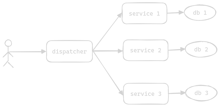
- the workers can be
- completely different services - for add recommendations, we request multiple services and then chose the best add for the user and show it to them
- same service with access to different data - e.g. one worker processes files 1 to 100, a second worker processes files 101 to 200 and so on. i think this is what is used in databases with sharding
- if one of the workers do not respond, we can aggregate the partial results from the other remaining workers
- we can also use a message broker in between the dispatcher and workers for decoupling. if it is not possible to return the result instantaneously, the dispatcher can instead send an id which the client can monitor
Execution Orchestrator Pattern
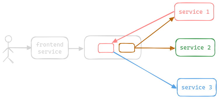
- imagine we break a monolith into microservices
- an extra “orchestration service” is used, which does not perform any business logic itself
- it performs complex flows by calling different services in the right order
- this is in a way like scatter and gather, but here we have a sequence of operations - not one operation sent down to all the workers. again, unlike in scatter and gather where all operations could be performed in parallel, we may or may not be able do that here, as result from one service might be used as a request to another
- the orchestration service maintains all the intermediate state till it is able to construct and return the final result
- what if the orchestration service fails midway / or after performing the entire flow but just before sending the response?
- the orchestration service can store all its intermediate state inside a db, so that if the client re initiates the request, another orchestration service can pick up from where the faulty orchestration service left
- the orchestration service also has logic around handling exceptions and retries - e.g. saga pattern
- for high availability, we can also deploy the orchestration service in a horizontally scaled manner and have it sit behind a load balancer
- orchestration service != api gateway - api gateways are meant to be dumb, while the orchestration service fully understands the context of a request
- best practice - the orchestration service is not meant for business logic - only for orchestration. the business logic is performed only by the various services sitting behind it

Choreography Pattern
- drawback of execution orchestrator pattern - changes in any of the services involves a change in the orchestration service
- this is called a “distributed monolith” - the orchestration service in the above example has become a distributed monolith because for e.g. multiple teams working on their own services might have to now change the orchestration service code together, again impacting organization scalability
- instead, the orchestration service is replaced by a message broker
- a message is put onto the message broker, and the services can subscribe to this message as needed
- they can then also put more messages into the queue as a result of which other services can subscribe to them
- this continues till the flow is complete
- since all this communication is asynchronous, all services are decoupled from each other
- even if one of the services is down, the flow can still continue and the relevant parts will still complete
- disadvantage - tracing the entire flow can become very difficult in case of issues, since we do not have a central orchestrator which was aware of all the steps during the entire flow
Patterns for Data Intensive Applications
Map Reduce Pattern
- simplified processing pattern
- by google around 2004
- we need to distribute the processing and huge datasets into several machines
- issues include -
- distributing the data
- parallelizing the workload
- scheduling execution on the different workers
- aggregating results
- recovering from failures
- solution - we model all problems using the map reduce model
- we pass the input data through map function, which outputs key value pairs
- then, the reducer receives all the values for a key, on which it can then perform some computation
- underneath, the map reduce framework takes care of all the issues we listed above - refer this for the entire working of map reduce. e.g. heartbeats mechanism might be used to ensure the worker is running. if this fails, the task would be rescheduled on another worker
- if the master itself fails
- the process can be restarted from scratch again
- the master can take frequent snapshots, so when a new master is spun up, it can restore from where the faulty master left off
- a backup master can run alongside the primary master, which stays in sync
- map reduce is great for cloud because -
- we easily get access to a lot of compute and storage
- map reduce is batch processing - so we can run on demand and pay as we go, and not pay for extra compute
Saga Pattern
- in microservices, we discussed how we should use one database per service
- with one database per microservice, we lose out on the acid transactions
- so, saga pattern helps us manage consistency across microservices using distributed transactions
- if there is a failure in any of the microservice, a rollback is performed on the other microservices by applying an operation which has the “opposite effect” of the original operation
- saga pattern can be implemented using -
- execution orchestration pattern - the execution orchestrator decides whether to proceed with the transaction or rollback the transaction on the previous service with a “compensating operation”
- choreography pattern - each service can either trigger the event for the next service if successful, or trigger the “compensating event” for the previous service if unsuccessful

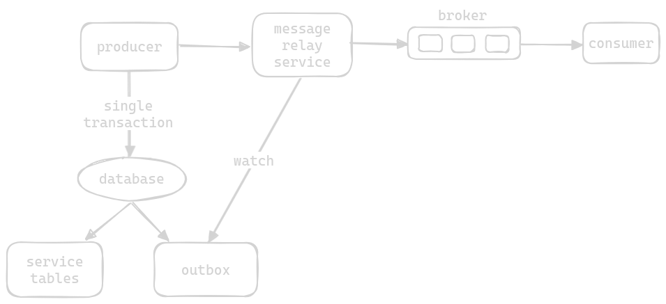
Transactional Outbox Pattern
- helps implement reliability in an event driven architecture
- e.g. a service needs to update something in its database and send a message to a message broker
- updating database and sending a message to a message broker is not an atomic operation
- so, if we for e.g. perform the database operation first, it might happen that the database is updated but the message is never sent to the message broker
- if we send the message first, the database might never be updated, but the message would have already been sent to downstream services
- extension of above - we can argue that with at least once semantics, we can always ensure that the message gets sent. issue -
- we successfully update the database and commit the transaction
- we fire the message
- our server goes down at this point - otherwise libraries of kafka etc are “intelligent” enough to resend the message if ack from broker is not received
- the message too gets dropped midway and does not reach the message broker
- to solve this, we use the “transactional outbox pattern”
- step 1 - it instead “as part of the same transaction” updates the actual data and inserts a new event ino an “outbox table”. either both the update and the insertion of this new event will succeed, or both will fail, since both of these are a part of the same transaction
- step 2 - another service called “message relay service” polls this outbox table and puts any new entries in this table onto the message broker
- step 3 - it then either deletes the event or marks it as sent
- issue 1 - “duplicate events” - just before step 3, the message relay service crashes. it then comes back up and again performs steps 2 and 3. this situation is called at least once delivery semantics
- solutions -
- the service logic is designed to be idempotent
- assume that the outbox table adds a unique id for every event, which the message relay service adds to the event it puts on the message broker as well. the consumer keeps track of the ids it has already consumed, and this way, it knows that when there is a duplicate event, it needs to discard it
- issue 2 - the database does not support transactions, e.g. non relational databases. step 1 of our solution relied on the fact that insertion into the outbox table and update to the regular tables can all be done under one transaction
- solution - instead add an outbox parameter to the object, which contains the list of events to be sent
{ "name: "...", "outbox": [ { ... } ] } - now, the message relay service can poll all objects with this outbox parameter and after adding the messages onto the queue, it can remove the outbox parameter from these objects
- issue 3 - ensure ordering of events. e.g. user registers and then cancels, but we receive the cancel request first (which is dropped since no user is found), and then the registration is processed - which means the cancellation process was ignored altogether. so, ordering of events might be important based on use case
- for this, use a sequence id when storing events in the outbox table. this way, the message relay service will always put the messages onto the broker after sorting them using this sequence id
Materialized View Pattern
- complex queries that involve different tables or maybe even different databases can be very slow - e.g. when we split our stack into microservices, the data is stored in different databases
- these complex queries also consume compute resources, thus increasing cost
- “materialized view” - a read only table is created with the data of the result
- consideration - additional storage cost
- two strategies to update -
- whenever the base tables get updated
- based on a schedule
- two ways to update -
- some databases support materialized views out of the box. most of such databases are efficient - they only take into account the modifications in the base tables, and do not recompute the entire materialized views from scratch
- we can programmatically compute this materialized view ourselves and store it in an optimized e.g. in memory database
- refer cqrs + materialized view pattern
CQRS Pattern
- cqrs - “command and query responsibility segregation”
- divide service into two different services -
- “command service” - mutation of data - inserts, updates and deletes
- “query service” - reads data and returns to the caller
- these services have their own databases as well - the command database can be optimized for writes - e.g. using an sql database, while the query database can be optimized for reads - e.g. using a nosql database
- cqrs is useful when we have both frequent reads and frequent writes
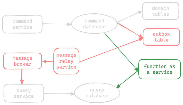
- “synchronization” - to keep the command and query database in sync, we can either use a message broker, or a function as a service
- using a message broker (in red) -
- an event is published via a message broker by the command service which the query service can consume
- now, the command service could have put the event into message broker directly. but, to prevent loss of messages, we can use the transactional outbox pattern
- using a “function as a service” (in green) -
- a function as a service is sitting between the command and query database
- it will only be triggered when there is a change in the command database
- once triggered, it will go and update the query database
- since it is a function as a service, it only runs when there are updates, thus saving us costs
- doubt - is this essentially the architecture for cdc tools like debezium?
- cqrs drawbacks -
- we can only guarantee “eventual consistency” between command and query database
- we have additional complexity for two different services and for the logic for synchronization between them
- cqrs + materialized view -
- e.g. when we split our stack into microservices, the data is stored in different databases
- this means complex services will have to hit different databases (via api calls to their services), which is slow
- so, we use one query service which receives events from “multiple command services” (multiple command services is the key here), and it stores the combined materialized view for all these services at one place
- e.g. one command service for courses, one command service for reviews
- and one query service for the materialized view, say an “enriched course”
Event Sourcing Pattern
- typically, data in databases is the current state - modifications override the previous state with new state
- sometimes, we need all the events that led to a state - e.g. show all the transactions for a user’s bank account
- so, we only store events instead of the current state
- events are “immutable” - we can only “append” events, not change existing ones
- event sourcing has high performance for write intensive workload - in normal databases in case of write heavy workloads, there is a high contention due to concurrent updates for the same tables and rows. with event sourcing, each write is “append-only”, which involves lesser locks
- to find the current state, we only have to apply or replay all the events
- we can also store the events in message brokers instead of storing them in databases, but querying message brokers is more difficult than querying databases
- now, replaying all events for all queries every time might not be efficient. so, we can take “snapshots” at certain periods. we still have all the history, but for deriving the current state, we only need records since last snapshot
- another popular pattern - cqrs + event sourcing
- the command service just puts the writes to the write events on to the message broker. it can even get rid of its own database
- the query service listens to these events and accordingly populates its e.g. in memory database with the snapshot we discussed about for faster reads
- another pattern being used here is event streaming
- remember - cqrs means eventual consistency

Software Extensibility Patterns
Sidecar and Ambassador Pattern
- apart from performing the core functionality based on features of the system, a service needs to do things like collect metrics, send its log events to a distributed logging service, connect to a service registry for the most up to date ip addresses of its downstream services, etc
- all these functionalities are also “common” across all our services - so we would not want to repeat ourselves
- one solution - we implement all this as a library, which all our services use
- disadvantage - different services might be implemented using different languages. so we would need to support the library for different languages, which is a lot of overhead
- so, we instead use “sidecar pattern”
- the sidecar is “isolated” from the main process - the additional function is run as a separate process / container on the same server
- the communication between the two is also very fast, since they run on the same host
- since the two use the “same resources” like file system, cpu, memory, etc - the sidecar can report the value for these resources easily
- the sidecar can now be implemented in any language of our choice
- after making the changes related to business logic in the main application, we do not need to test the sidecar

- “ambassador pattern” is a particular type of sidecar pattern
- in ambassador pattern, the ambassador acts like a proxy
- the service just sends requests to the ambassador, which then forwards these requests to the actual server, by handling things like authentication, retries, circuit breaker, etc
- using the ambassador pattern also allows us to perform “distributed tracing” easily
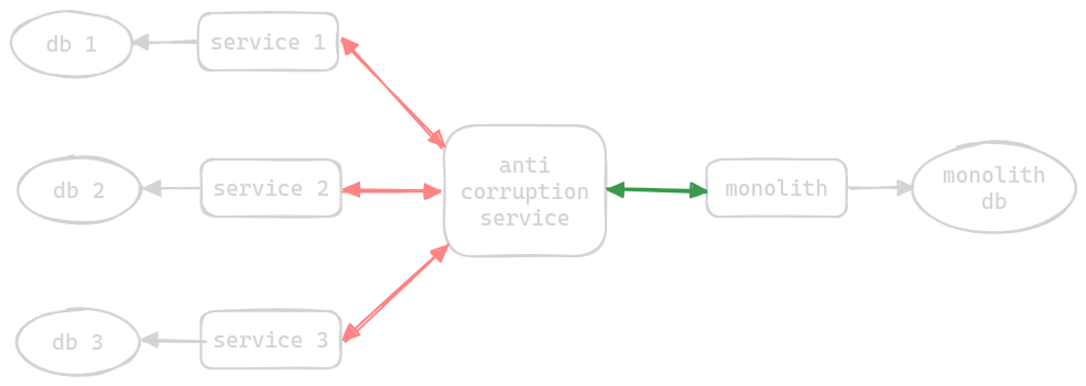
Anti Corruption Adapter / Layer Pattern
- when we migrate from an old monolith to a new set of microservices
- the new set of microservices need to temporarily interact with the old monolith till the migration is complete
- this means that code for old apis and protocols is scattered in the new microservices
- so, we deploy an “anti corruption service” in between, which performs the translation between the new microservices to the old monolith (both request and response, to and from both microservices and monolith)
- sometimes, the anti corruption layer can be “temporary” or sometimes “permanent” when we cannot get rid of some parts of the legacy system - e.g. downstream services use the legacy application for reporting and are not ready for a migration yet
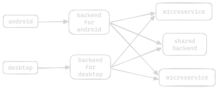
Backends for Frontends Pattern
- usually, we have a separate backend in front of our microservices, to serve the frontend
- now, the frontend just has to interact with this one backend, which performs the logic of relaying the request to the right microservice
- assume we have to support multiple frontends like desktops vs mobiles. they interact with the api differently -
- e.g. mobile screens have lesser real estate so display lesser data than desktops
- mobile devices have lesser resources (ram etc) compared to desktop
- mobile app owners might want additional features like scanning barcode, only want products available in a particular location, etc
- now, our backend service starts to become a monolith - it has to support the additional features for the desktop, mobile app and the shared features between the two
- so, we use the bff or “backends for frontends pattern”
- we use a separate backend for each frontend
- each backend now stays slim, and allows its frontend to make use full use of its feature set
- we can now scale each backend individually as well - more server side computation might be needed for mobile apps then for desktops
- how to implement the shared functionality in these backends, e.g. login and register
- use a shared library - this pattern usually does not scale well, because -
- any change in this shared library affect all the backends that use it
- there is also often a “lack of ownership” with such shared libraries
- spin up another common service called a “shared backend service”
- use a shared library - this pattern usually does not scale well, because -
- the “user agent” header in requests helps us tell the device a request is coming from, and by placing an api gateway in front of these backends, we can decide which backend to route the request to based on the device
Reliability, Error Handling and Recovery Patterns
Throttling and Rate Limiting Pattern
- e.g. one client bombards our systems with multiple requests. this leads to high cpu and memory utilization of our resources. thus, our response time increases / services become unavailable, and we would be unable to serve other clients, thus violating our sla etc
- using “throttling and rate limiting”, we set a limit on the number of requests in unit time / bandwidth (amount of bytes) in unit time
- “server side throttling” - we as the service providers would like to limit our systems from over consumption
- server side throttling use case - we can have different grades of customer - premium and so on, and we would like different limits for these different customers
- server side throttling con - the rate limiter can be overwhelmed by so many clients / it needs to be well scaled
- “client side throttling” - we are calling external services and would like to set limits on the number of calls made to such services
- client side throttling use case - throttle requests for different services at different levels, based on their quotas
- we can handle this using different strategies -
- “drop requests” - status code is 429 (too many requests)
- “slow down the service” - queue the requests in a queue and process them later
- “degrade the service” - e.g. a video streaming platform can reduce the resolution of the video
- types of throttling -
- “hard throttling” - put a hard limit on the no. of requests. when a request exceeds the limit, it is discarded
- “elastic / dynamic throttling” - number of requests can exceed the predefined limit if the system has excess resources. so, there is no upper limit as such
- use cases -
- prevent dos attacks, brute force password logins, etc
- prevent resource starvation
- managing “quotas” when there are multiple users accessing the same resource
Retry Pattern
- we retry the same operation in case of a failure
- we should retry only if the failure is temporary and recoverable - e.g. not a user error like unauthorized, bad request, etc
- if the request succeeds on a retry, we were able to hide the internal issues from the user successfully
- so, we need to pick the right “delay” and the right “backoff strategy” for this delay
- “fixed delay” - the delay between subsequent requests stays same - 100, 100, 100, 100
- “incremental delay” - the delay between subsequent requests increases linearly - 100, 200, 300, 400
- “exponential backoff” - the delay between subsequent requests increases exponentially - 100, 200, 400, 800
- we can add “jitter” - a random delay between these delays
- e.g. for incremental delay, instead of calculating delay using i * 100, we do i * (100 + random(-15, 15))
- reason - clients might end up retrying at the same time, thus causing the retry storm. this jitter helps prevent the retry storm
- “retry storm” - some instances of the service were unhealthy, we bombarded the remaining instances with our retry requests and made the entire service unhealthy
- apart from the backoff strategy and delay, we can also configure how many times to retry / how long we should keep retrying for
- note - the operation we retry should be idempotent - the client will not know if the request was lost or the response - and if it was the response that was lost, we cannot retry a non idempotent operation
- retry pattern can be configured in the ambassador pattern or implemented via popular libraries
Circuit Breaker Pattern
- “cascading failures” - e.g. in a microservice architecture, a failure in one microservice, say due to a new bug, causes a failure in the entire chain. service a -> service b -> service c -> service d, and slow responses from service d causes all the other services to slow down
- “circuit breaker” - we now relay our network calls via this circuit breaker instead. this way, the circuit breaker can monitor the success rate of the calls it is making. if the circuit breaker notices that too many of the calls that it is making are failing, it would stop relaying the request and immediately return a 503
- assume a service was struggling with too many requests, and now because of slowness, even more requests are queuing up, thus causing all its replicas to go down due to overload. when we use circuit breakers, we do not forward requests to this faulty service, thus giving it a chance to come back up
- we were able to recover from temporary and recoverable issues using the retry pattern
- retry pattern is optimistic, while circuit breaker is pessimistic
- if the errors go above a certain threshold, the circuit breaker does not even allow the requests to go through
- this way, we save on resources and time from calling a service which might anyway be down
- after being in the open state for some time, the circuit breaker automatically goes into the “half open state”
- it allows a small percentage of requests to go through
- if they succeed, the circuit goes back into closed state
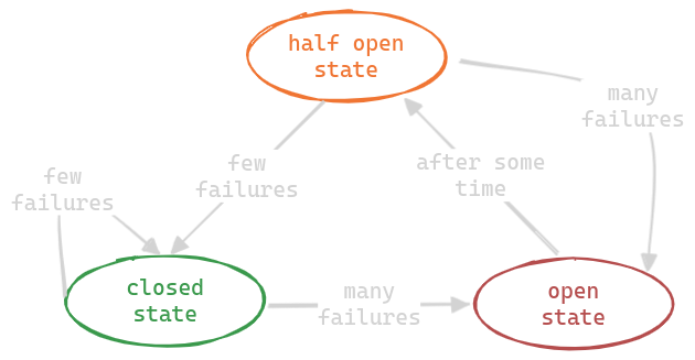
- we can either drop the requests, or save it in one place to be retried later. this approach is called “log and replay”. it might be needed for requests that are not just simple get requests, but require calling a mutation endpoint on another service
- we should configure different circuit breakers for different services
- we can also replace the half open state with “asynchronous pings / health checks” to the service - once the health checks start passing, we can mark the circuit as closed. we get rid of the half open state in this technique
- this too can be configured in the ambassador pattern or implemented via popular libraries
DLQ (Dead Letter Queue) Pattern
- helps handle errors involving message brokers
- producer error - the producer cannot put the message on the broker because the queue is already full, the message is too big, etc
- consumer error - the consumer cannot process the message due to some data discrepancy
- so, we introduce another special topic or queue called the “dead letter queue”
- two strategies -
- so, both the producer and consumer on encountering an error move the message to the dlq themselves
- the message broker itself is configured to move messages to the dlq
- producer errors can be identified easily by the message broker - queue is full, message is too big, etc
- for consumer errors, if the message would not be consumed for a long time, message brokers can conclude that the messages are not getting acknowledged, and it can move these messages to the dlq
- best practices -
- add the reason e.g. stacktrace to the message headers before moving the message to the dlq
- use aggressive monitoring and alerting for messages in the dlq
Deployment and Production Testing Patterns
Rolling Deployment Pattern
- when deploying a newer version of our application to servers, we bring down the servers during a “maintenance window”
- sometimes, we might not be able to bring our servers down entirely, e.g. during an emergency release, which is not during the maintenance window
- steps -
- stop the load balancer from forwarding traffic to one server
- upgrade the application on this one server
- run some tests on this new version if needed
- allow the load balancer to send traffic to it again
- keep redoing this one after another till this is done for all the servers
- this way, our application is always up
- when releasing, if we notice any issues / errors, we can follow the same set of steps to perform a rollback
- advantage -
- no extra cost for hardware
- most widely used due to its simplicity
- drawbacks -
- it can result in “cascading failures” e.g. suppose the new servers start failing. now all the traffic will go to the old servers, which can inturn start failing as well due to “overload”. now, this brings down our entire service
- if the new version is “incompatible” with the old version, there might be issues - e.g. db schema changes
Blue Green Deployment Pattern
- “blue environment” - we keep the old version of our servers running as is throughout the release
- “green environment” - we deploy the new version of our servers to this environment
- we carry out tests on the green environment
- if the tests etc run fine, we shift the load balancer to point to the green environment
- if we see a failure at any point, we can shift the load balancer back to point to the blue environment
- finally, we can terminate the blue environment once we are done

- advantages - both disadvantages of rolling deployments -
- both environments have an equal number of servers, so the issue of cascading failures is prevented
- we can only run a single version of our software at a given moment, so the issue of incompatibility is prevented
- disadvantage - both advantages of rolling deployment
- extra cost for hardware
- complicated to implement
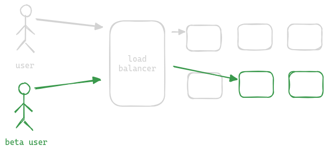
Canary Testing and A/B Testing Deployment Pattern
- “canary release” - borrows patterns from both rolling deployment and blue green deployment
- we deploy the new version of the application to a small set of “existing” servers (instead of one by one to all existing servers like in rolling deployment)
- it is considered safer than rest of the deployment patterns because -
- for canary release, the performance etc is monitored for much longer than in other patterns
- only beta users get the traffic to the new servers - this can be done by the load balancer for e.g. by inspecting the origin header
- “ab testing / deployment” - ab testing works just like canary release
- however, in this case, we deploy with the motive of rolling back to the old version
- use case - we test the new feature, but are not fully ready with it to go into production
- sometimes, the users who are a part of this ab testing do not even know about it - they might be seeing new features and can be asked for feedback about it. this helps with genuine feedback
Chaos Engineering
- “chaos engineering” deliberately injects random failures into our production systems
- it helps us find single points of failure, performance bottlenecks, etc
- advantage -
- system becomes more reliable with time
- development team becomes more proficient in monitoring and debugging production issues
- the types of failures we can inject - terminate random services, inject random latencies, etc
- e.g. of a tool - chaos monkey by netflix
Multi Tier Architecture
- organize system into multiple “physical” and “logical” tiers
- “logical separation” - different tiers handle different concerns
- “physical separation” - allows each tier to be separately developed, scaled and upgraded

- most common architecture - “three tier architecture”
- tier 1 - “presentation tier” - the ui on web browser, mobile app, desktop gui, etc
- it takes input from the users / shows them the relevant output
- it does not contain business logic
- tier 2 - “application tier”, “logic tier”, “business tier”
- it has all all the business logic based on the features of the system
- tier 3 - “data tier” - responsible for storage and persistence
- it can contain files and or database
- this three tier architecture fits most use cases
- it allows for easy horizontal scaling
- tier 1 does not need any scaling since it runs on user devices
- tier 2 can run behind a load balancer and be scaled easily if it is stateless
- tier 3 can also be scaled well using techniques like partitioning and replication discussed here
- drawback of three tier architecture - tier 2 becomes a monolith
- monolith drawbacks
- high resource (cpu and memory) consumption
- harder to maintain codebase
- a fault can result in the entire system being down
- so, three tier architecture is good for companies who have a small codebase
- “two tier architecture”
- tier 1 - has both ui and business logic
- tier 2 - data tier
- “four tier architecture” - a new tier in the three tier architecture is introduced between tier 1 and tier 2 for api gateway, to address caching, security, etc
Multi Layer Architecture
- “closed layers” - communication cannot be skipped between the layers
- this helps keep the layers loosely coupled, and is usually preferred
- “open layers / layer bridging” - when a layer can be bypassed, it is called an open layer. e.g. imagine that layer 1 can directly communicate to layer 3
- open layers increase the cost of maintenance due to the increase in the number of dependencies
- multi tier != multi layer architecture
- multi layer is when the same application is broken into different modules
- however, it will still run as a single unit during runtime and will be a single tier architecture
- in a multi tier architecture, the different tiers run on different machines altogether
MVC Architecture
- mvc - “model view controller”
- “model” - maintaining the state of application
- it is implemented as a set of classes that represent the data and the operations we can perform on it
- “view” - renders the user interface
- implemented using “templates” / scripts that generate the html, css and js
- “controller” - receives the request from the view, receives the response from the model and finally, sends it to the view
- advantages - separation of concern, allowing for easy development and testing
- disadvantages - abstractions between model and what user sees, making it less intuitive
MVVM Architecture
- mvvm - “model view view-model”
- the controller in mvc architecture gets replaced by “view-model” in this case
- difference - the “view-model” and view communicate using “data binding”
- “data binding” - a change in view automatically calls the right methods in the model-view etc
- while view and controller are more tightly coupled, view and view-model are more loosely coupled
- note - my understanding is mvc is more for traditional web application backends, while mvvm is more for ui applications like angular
- typically, we do not need to implement dom manipulation, event handling etc manually
Microservices Architecture
- recall monolith drawbacks - high resource consumption, hard maintainability, lack of fault tolerance. microservices removes all these drawbacks -
- “independently deployable”
- each service can be easily scaled horizontally
- unlike monoliths which would relatively be much more resource intensive, microservices are much more efficient to scale and maintain
- we can make the right choice for tech stack for each microservice based on use case
- “loosely coupled” - helps with organization scalability by breaking down codebase. now, a small team is responsible for this codebase
- helps with fault tolerance, since faults are now scoped to a smaller component
- “independently deployable”
- disadvantage -
- overhead increases around testing, debugging issues, etc
- latency increases - more so if we do not ensure loose coupling when decomposing the service
- important - distributed transaction management is much harder when compared to using a single database
Migration to Microservices
- e.g. assume we have a three tier architecture for our e commerce application, and would like to split the second tier into microservices
- 3 principles to follow when creating microservices -
- “cohesive” - elements that are tightly coupled to each other should stay together inside the same microservice, so that each microservice can be developed and maintained independently
- srp or “single responsibility principle” - a microservice should only do one thing. this removes “ambiguity” around which microservice should own what piece of functionality
- “loosely coupled” - there should be minimum communication required between different microservices, and a microservice should be able to do its task independently
- size of a microservice does not matter, it is the 3 principles above that should influence decisions
- popular decomposition techniques -
- “business capabilities” - identify what provides value to business. take stakeholders pov
- “domain / subdomain” - also called “domain driven design” - instead of looking at it from a business side, we take the developers pov in this. types of domains / subdomains are -
- “core” - key differentiator / features of system
- “supporting” - integral in delivering the core capabilities, but not a differentiator - e.g. shipping
- “generic” - not specific to any business - can even be bought off the shelf - e.g. payments
- “incremental and continuous” approach should be used -
- identify the parts which will benefit the most from this migration
- parts requiring frequent changes - most important
- parts that have scalability issues
- “strangler fig pattern” -
- we keep a “strangler facade”, which can be implemented using an api gateway, that sits between clients and our backend systems
- now, the api gateway initially routes requests to the monolith
- when the microservice is ready, the api gateway is switched to route requests to the microservice instead
- we can also use canary testing / ab testing pattern here to direct a part of the traffic to the new decomposed microservices and slowly increase this percentage
- finally, the components of the microservice are removed from the monolith
- because of our incremental and continuous approach, the monolith keeps getting smaller and smaller
- original monolith should have a good “test coverage”, to ensure this split does not break anything

Microservices Best Patterns
Database Per Microservice
- if we use the same database across different services, it results in “tight coupling” - recall that one of the principles of microservices was loose coupling
- e.g. if the schema changes due to one microservice, this change needs to be propagated to other microservices that use the same database as well
- the database of another microservice cannot be accessed directly - they have to go through the api of the owning microservice
- advantage - we can chose the database optimized for the workload of the microservice
- downsides -
- “added latency” - sending an additional request to the microservice and parsing the response is slower than accessing the data directly. to prevent the overhead of communication, we can cache the response of the responding microservice in the requestor microservice. however, this caching makes our system “eventually consistent” from “strictly consistent”
- cannot perform joins as easily now, since data is spilt across databases - solved by cqrs
- we lose out on acid transactions - performing a distributed transaction is very hard - solved by saga
- “data duplication” - data is now duplicated across microservices - e.g. product information might be duplicated in orders service
DRY Principle
- dry - don’t repeat yourself - we should not repeat ourselves
- this way, we only need to change the logic in one place
- by this logic, we might want to package the repeated logic of microservices into a shared library
- but, this is not a good practice - dry does not hold for microservices
- it introduces “tight coupling” - recall that one of the principles of microservices was loose coupling
- because for e.g. if a team makes changes to the shared library’s apis, these changes need to be communicated to the other teams as well
- another drawback - “dependency hell”
- e.g. a microservice uses v1 of a library directly
- its shared library uses a different version (v2) of the same library
- now, the microservice needs to upgrade the library to v2 because of the shared library, retest this, etc
- solutions -
- we can increase the boundary of some microservice to include this shared logic, and other microservices call this microservice for the same
- we can spin up a new microservices containing that shared logic
- we can use the sidecar or ambassador pattern as well for e.g. for observability
- note - shared libraries is a good pattern for sharing data models - request and response dto
- for this, we have techniques like code generation tools that can generate implementations for all languages based on an “interface definition”
Structured Autonomy
- myth - teams can chose their own tech stack, databases, tools, etc
- doing things differently in different microservices around building, testing, maintaining codebase, etc introduces a lot of overhead
- autonomous is allowed but under certain boundaries, hence the term “structured autonomy”
- tier 1 - “fully restrictive” - should be uniform across the whole firm - e.g. monitoring and alerting, ci / cd, etc
- tier 2 - “autonomy within boundaries” - database technologies
- tier 3 - “complete autonomy” - e.g. release process
Microfrontends
- we can split the monolithic frontend just like we split microservices - based on domain / subdomain or based on business capabilities
- each microfrontend is an spa
- all these microfrontends are assembled inside a “runtime container”
- the runtime container can also handle things like authentication / authorization
- now, each microfrontend has its own ci cd and can be released independently
- best practices -
- microfrontends should be loaded at runtime, and not as compile time dependencies, otherwise the release schedule etc would still be tied to each other
- sharing state should not be done - it is equivalent to sharing a database in microservice. we should instead use custom events, pass callbacks, use address bar, etc
Event Driven Architecture
- three actors are involved - producer, consumer and event
- use event driven architecture when we can classify actions as “fire and forget” / “asynchronous”
- events are immutable
- events can be stored indefinitely in our system (unlike requests in synchronous communication)
- unlike in the “request response model”, where the sender needs to be aware of receiver’s api, data models, url, etc. in event driven architecture, the publisher does not care and is not even aware of its consumers. this helps achieve “decoupling”, one of the principles in designing microservices
- refer message brokers for more points, advantages and examples of this approach
- 2 event delivery patterns are supported - event streaming and publish / subscribe
- “event streaming”
- the message broker acts like a permanent storage
- the consumer can view any number of past events based on use case
- optionally, the message broker can remove the events from storage after a period of time
- “publish / subscribe”
- the message broker acts like a temporary storage
- this means “replayability” is not supported unlike event streaming
- only new events from the point the consumer joins are visible
- allows for implementing patterns like event sourcing, cqrs, saga
Message Delivery Semantics
- failures can happen during multiple stages - (draw quickly in interview using arrows)
- the producer sending the message to the broker fails
- the producer sending the message succeeds but the acknowledgement from the broker fails
- the message broker sending the message to the receiver fails
- the receiver receiving the message succeeds but the processing fails
- the receiver processing succeeds but the acknowledgement to the broker fails
- this is what the “message delivery semantics” help addressing
- “at most once delivery” -
- the producer does not wait for acknowledgement from broker - so, if the message is lost from producer to broker, we loose the event
- the consumer sends the acknowledgement immediately to the broker before starting its processing - so, if the consumer crashes after receiving the event, we loose the event
- use case of at most once delivery - when we are fine with data loss
- we can extrapolate lost events - e.g. location updates in a ride sharing service
- advantage - at most once delivery has the least latency and cost
- “at least once delivery semantics” -
- the producer will resend the event if the acknowledgement is not received
- consumer sends the acknowledgement to the broker only after successfully processing the event
- so, it can result in duplicate events if the message is received (and potentially processed) but the acknowledgement is lost
- use of at least once delivery - data loss is not acceptable
- e.g. reviews can be overridden if received multiple times
- disadvantage - more latency, e.g. broker and producer need to wait for acknowledgements etc
- “exactly once delivery” -
- very difficult to achieve
- we generate a unique id / the message broker does this for us automatically
- then, the message broker checks if it has already received this id in the past by checking its log
- the consumer needs to check in its database if the event with this id has already been processed, and accordingly handle the event
- understand that the consumer can still receive the message multiple times like in “at least once delivery”. however, our consumer code logic is smart and if it sees a duplicate, it simply ignores it and sends an acknowledgement, thus avoiding processing the event multiple times
- so, my understanding - exactly once from producer to message broker might be guaranteed by message broker, but message broker to consumer needs to be guaranteed by us?
- e.g. processing of payments need to happen exactly once
- note - kafka guarantees exactly once when transferring data between kafka topics
- so, my final understanding -
- for ensuring that the message reaches the broker from the producer, use transactional outbox pattern
- for ensuring that the message reaches the consumer from the broker, use at least once delivery semantics
- to ensure exactly once, maintain the processed ids of events in the consumer database
Testing
- unit test -
- test a class / method / module in isolation
- advantage - cheap to maintain, fast to execute
- we should have a lot of unit tests
- disadvantage - give the least confidence about overall system
- integration test -
- verify the different systems we integrate with, e.g. databases, message brokers, etc
- disadvantage - run slower
- we should have fewer integration tests
- give more confidence about our system
- functional / end to end test -
- run on the entire system
- works from an end user perspective - so each test should test the entire user journey
- very slow to run
- we should have very few end to end tests

- in microservices, for integration tests, we can use “lightweight mocks” for our upstream services
- disadvantage - mocks will not help us identify changes to the api of the actual upstream services
- so, we can use “contract tests” alongside the integration tests
- the idea is that the downstream service saves the results of its integration tests (the requests and responses it expects) in a contract file
- these tests are then run on the actual upstream service - the requests are replayed, and the responses are asserted using the expected response of the downstream service
- contract testing can be used for asynchronous communication as well - the downstream service tells the message it expects, and the upstream service asserts that the message is triggered when the appropriate functionality is called
- so, contract tests are basically a great addition / alternative to integration tests by themselves in microservices
- e.g. spring cloud contract
- if our company cannot afford functional / end to end tests, we can directly test in production
- using blue green deployment, we can test in the blue environment before we switch traffic of the load balancer from blue environment to green environment
- canary testing
Hexagonal Architecture
- “hexagonal architecture” is also called “ports and adapter architecture”
- separates core functionality of system from its external dependencies
- “core domain” - contains the application logic and entities for the core business
- “adapters” - components that connect the core domain to the outside world i.e. databases, web services, etc
- “ports” - interface / contract between the core domain and adapters
- “drivers” - concrete implementation of the ports
- advantage - easy replacement of an adapter without changing the core domain
- also, the modularization helps with effective unit testing etc
Serverless Architecture
- applications are built using cloud services, thus abstracting the underlying infrastructure away
- this makes it easier and more cost effective to deploy these applications
- “cloud functions” - small self contained pieces of code
- cloud functions are typically “stateless” i.e. they do not share state between invocations
- “event driven triggers” - they respond to specific events, e.g. change in database
- “autoscaling” and “pay per use pricing”
- disadvantages -
- “cold starts” - experience a delay when first invoked, which impacts performance
- debugging becomes more difficult, since we do not have access to the underlying infrastructure
- limited control, dependency on the cloud provider, etc